Pages

Friday, September 28, 2012

0031 Components Continued


Some may be wondering WHY I am revealing all these Geometric Drawings ?

The reason is a bit like, wanting to Skipper a huge Oil Tanker or the largest Passenger Ship.

Before we can perform such a task, we need to know all the components involved
in taking command of such a vessel.

To posses or take command of the Soul is also a bit like that Ocean Liner.

So we 1st need to now the Components in the "Operating System" and what each
Component is for and the Language involved.

It's a bit like reading or writing a book.

If we first don't know the language, we can't read or write a book.

So please bear with me, as there is much to show 1st, before I get into the Communication
and programming side of things.
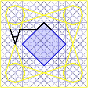
The Square "Frame", used as a "Geometric Instruction"....


Can also be "Partitioned" into 4 "Primary Squares" as well as "The 9 Gates".

First "The 9 Gates" (again)...


and Now, the 1st Generation "Squares" on their side.


These are the 4 sub sectors of each "Stack" in the "Temporary Library" Construct.

a.      The Upper Left is the Program Register.
b.      The Upper Right is the Control Register.
c.      The Lower Left is the Picture or Data Register.
d.      The Lower Right is the Scratch Pad Register.

In each of these Registers we can find "The 9 Gates" once again, but this time
involving another generation, rather than the Complete and "Stand Alone" Programs.


and

And in each of these we can find another Generation of "The 9 Gates" again.


Here is an enlarged drawing showing a Single Module.


And in addition, yet another Set of Overlapping "9 Gates" in a larger generation.


Here is an enlargement, showing the Overlapping "9 Gates" Modules.


and here, 4 of the "9 Gates" Overlapping.


This Drawing shows ALL these "Partitions" (Involving "The 9 Gates" Modules)
Inside the Large "Square" Containing the 1st Generation "9 Gates".
A total of 120 excluding the Center "Square" of the 121 "Partitions".


This next drawing, reveals the Registration of the "Line Work", with relation to the small
"Octagonal Registers".

There is another Set of "Squares" which involves the 4 "Partitions"
of the "Temporary Libraries".

So back again to the Geometric Instruction...


Looking at the Library "Partitions" rather than "The 9 Gates" used to Load
Programs.
Shown below, the "Program" Register and the "Scratch Pad" Register.


And here revealing the smallest Registers, involving the "Temporary Libraries".
Note there are 144 (12 x 12) "Squares" in this generation.


Here being displayed, as though a "Checkerboard"


Next showing again the overlapping 16 (4 x 4) "Squares" of "The 9 Gates" modules.


And here the overlapping 16 (4 x 4) "Squares" of "The 9 Gates" modules,
also shown in the form of a "Checkerboard". Note the Difference between
the 2 "Checkerboards" ?


The following Drawing, is an Enlargement of the above Drawing, showing
some of the "Squares".


If we introduce the "Partition" of the YELLOW "Squares" as shown below....


Then we find a Single BLUE "Square", accessible in each of the YELLOW "Squares".
The "Square" in each of the YELLOW "Squares"  is the "Primary Accumulator"
for Each of the YELLOW "Partitions".


But if we consider each of the YELLOW "Squares",  and the other "Squares",
BLUE "Squares" we can be find other Locations using different Line Work.


Now if we consider One of these Registers...


"Partitioned" into its sub Components Starting 1st with these 4 "Locations"....


These 4 Sub Registers, can be Moved around in the "Square" containing them...

Here are a few of the different Combinations and "Color Coded" examples.

The BLUE "Square" represents the "Importand the YELLOW "Square"
the "Existing" Program.

16 examples of Different Combinations are shown in this next Drawing


These "Squares" are another Example of the Geometric Programming "Instructions"
used in the "Processing Construct".

This type of "Geometric Language", is often used in part of the "Communication",
also used in the "Video Interfaces".

Usually as a "String" of coloured "Squares", letting the other end of the mind,
know what it wants to do in the process.

I will be going into this a little later on, but at this stage, I just want to reveal some
of the "Componentsof the "Geometric Language".

The Same "Language" can also be found in the Different Generations,
within the "Processing System".

This is the next Larger "Generation" ...


"Partitioned" into Locations (4 Corner Locations in the Drawing Below)


The Drawing below, revealing another 16 Examples but in the next Generation up...


There are many many more "Combinations", but I guess you get the General Idea
from those shown above?


Now for the Smallest Generation of this Group of "Generations"..

The "Squares" are ½ the size again, but this time GREEN "Square" Frames are shown.

GREEN Represents the Component "Contents" of a Program.


And inside the YELLOW "Squares" we can also be find the GREEN "9 Gates",
used for the Loading of these Components.


This completes the "Square" Registers on their sides (The Main "Temporary Libraries")
for now, used in both the "Video Interfaces", as well as Directly between the 2 Ends
of "The True Mind" without the aid of a "Video Interface".

In my Next post, I will reveal the 2 Outer "Partitions" (Left & Right "Partitions") used
in this "Video Interface" and go on to revealing other Components.


NOTE;
To gain the full understanding, please Start this "Thesis" from the beginning at 0001
if you haven't already...

Tuesday, September 18, 2012

0030 Components of the Mind Video Interface


In this Post I will Identify some of the Registers in this particular Format.


Here the same is shown instead, in Drawing Form superimposed on The Eye Matrix
"Partition Map".
Note it portrays the Mid Section. This is One of 3 Locations. The mid-section involves both
the "Upperand "Lower" Programs. (Worlds)


The next Drawing shows the "Upper" Program Location.


And the "Lower" Program (Involving the end Experience of your body and Environment
i.e. Universe)


The "Interface Video Screen" is divided into "Partitions". The mid-section
having 72 "Partitions".


The Hole Eye Matrix "Partition Map" has 144 "Partitions".


The "Mid Section" shown in Drawing 004 is divided into numerous "Primary"
Components.

This Frame is the "Instruction" for the Area used in Loading Programs and Editing,
regarding "Communication" between the 2 Ends of "The True Mind",
i.e. "Awareness" or LIFE.


Whereas this Format referred to as "The Ogdoad" (8 Sided Polygon) is used in Editing
the experience itself.


Now back to the Components of the 5th Drawing involving the 7th Drawing
in this Post again.

This next Drawing shows the "Left Location", in the Mid-section shown
in the 11th Drawing in this Post.


And the Right Location, in the Mid-section shown in the 11th Drawing in this Post.


And The Center Location, in the Mid-section shown in the 5th Drawing in this Post,
showing the 36 "Partitions" of the 144.


And in this next Drawing showing the 3 Primary "Partitions" when the BLUE "Frame"
is in the Center Location.

This Center "Partition", Indicated by the BLUE "Square" can be "Partitioned"
in several different ways.


I have shown how it can be "Partitioned" into 36 Small "Partitions" but it can also
be "Partitionedinto 9 Larger "Squares" too.

The 9 Larger "Partitions" inside this BLUE "Frame" was referred to as
"The City of 9 Gatesin the ancient writings.

This "Partition" Format is used to "Import" Programs from the "Main Temporary Libraries".


These are the Functions of each "Square" which are Registers ("Temporary Memory"
Locations) used in "Communications" between the 2 Ends of the Mind (Your Mind)

1.    The Upper Left is the Program Register.
2.    The Upper Right is the Control Register.
3.    The Lower Right is the Scratch Pad Register..
4.    The Lower Left is the Picture Register or Data Register.

5.    The Upper Center Register is the Upper "Running Program" Reg. involving Images
        & the Written Program.
6.    The Left Center Register is the "Written Program" Register.
7.    The Lower Center Register is the Lower "Running Program" Reg. involving Images
        & the "Written Program".
8.    The Right Center Register is the "Running Program" Out-Put Register.
9.    The Center Rgister ids the "Primary Accumulator" ALL "Communications"
        passes through between the 2 "Ends" of the Mind.


This is a Drawing showing the "Outer Permanent Libraries".
The "Hexagonal" Polygons are the "Geometric Instructions" for the "Permanent Libraries".

Remember we are revealing a "Communication Program" of "The True Mind".


And in this one a 6 pointed "Starwhich is One of the Formats used for "Importing"
anything from the "Permanent Libraries".


And here is the [u]other[/u] set of "Permanent Libraries". (Rotated 90°)


And the "Star" Rotated 90°...


This next Drawing shows the 2 Sets of "Hexagons", One overlaid on the other.


The 2 overlaid 6 Pointed "Stars" was the Inspiration that led to the establishment
of the 4 Great "Squares" in the 4 Corners.


Shown again here Establishing the Greater "9 Gates", which contain a copy
of the Data Imported from the "Permanent Libraries".


The Horizontal and Vertical Line Work in the "Stars" transfer the "Outer" information,
in this case ALL the chosen Data in the Library, to the 4 Corner "Squares"
via the Line Work.


And the Points of the "Stars", Transfers the "Inner" Contents of the "Running Program"
from the same Libraries chosen by the Programmer.
And in this Drawing below, shows the Contents Libraries of the "Running Program".


Along the Horizontal and Vertical Line Work of the "Stars", can be found 8
Large Octagonal Registers.
These Form 8 of the Locations involved in the "9 Gates". The Center Octagon
being the "Primary Accumulator"


This next drawing shows the Greater "9 Gates" which retains Data Copied from
the "Permanent Libraries".


And this Drawing shows the "9 Gates", involving the "Temporary Libraries"
containing Data "Imported" from the Hexagonal "Permanent Libraries".

This is in the BLUE "Square Frame" shown here in the Middle of the "Video Interface"
of the Mind, showing here the Communication "Octagonal" Registers.


And here showing the "Octagonal" Registers involved in the "Running Program".


These are the "Square" Registers, Containing either the "Written Program"
or "Images" used in the Program or both in the "Main Temporary Libraries".


And here the Temporary "Running Program Libraries".


Here are a couple of Geometric "Instruction" Glyph's, from some thousand Glyph's
used in the "Written Program".

The BLACK "Glyph" shown in this next Drawing, is a Geometric "Instruction",
which "Enables" the 2 Upper "Secondary Accumulators".


And showing in this next Drawing the 2 "Registers" which have been "Enabled".


These are the 2 "Octagonal" Registers, for the "Square" Registers shown in
the above Drawing.


Here is another Geometric "Instruction" Glyph which "Enables" a group
of 3 Registers.


This next drawing shows the Geometric "Instruction" Glyph which "Enables"
the "ControlRegister of the "Contents" Register.


And the Geometric "Instruction" Glyph which "Enables" the Program of the "Contents"
Register.


Shown in this next Drawing is the Geometric "Instruction" Glyph which "Enables"
the Upper "Control" Register of the "Running Program" of the "9 Gates".


And the Geometric "Instruction" Glyph which "Enables" the Upper "Program" Register
of the "Running Program" of the "9 Gates".


This Geometric "Instruction" Glyph Links the "Program" Register with the Primary
"Octagonal" Register which displays the "Written Program" in a "Stackform,
Frame by Frame.


And showing the "Link" made in this Drawing below.


And another similar Geometric "Instruction" Glyph but in this case involving different
sub Registers of the same "Program" Register.


And showing the "Link" made in this Drawing below.


NOTE;
To gain the full understanding, please Start this "Thesis" from the beginning at 0001
if you haven't already...