
I have been describing.
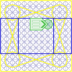
This Drawing shows the "Communication Format" pointing to the "Primary Accumulator",
and as it is on the Right Hand Side of the "Primary Accumulator", it refers to the "Output"
sub Register of the "Primary Accumulator".

And when the "Communication Format" is on the Left Hand Side, pointing to
the "Primary Accumulator", it refers to the "Written Program" Input sub Register
of the "Primary Accumulator".
of the "Primary Accumulator".

And if The "Communication Format" is NOT pointing to any Register, it refers to
Register behind it.

The "Communication Format" involves Rectangular "Windows", used to "Write" to the Register.
This Particular Format shown below, has 3 "Windows" which are;
a. The Upper Program Register.
b. The Mid Register where Perusing and Editing takes Place.
and
c. The Lower Register involving the Experience at the time.

Here is an Enlarged Drawing, showing the "Communication Format's" Registration
of its "Components".

This next Drawing shows its "Primary Mask" removed, so the Registration of the Rectangular
"Windows" is made more Revealing.

The "Arrow" shown in the Drawing, shows the Direction the Letters "Increment" in
from a Register on the far right of each of Window, in the "Communication Format".
The Next Drawing, shows the Mid "Window", being "Written" to.
The "X's" represent the letters.
The "X's" represent the letters.

Note in the above Drawing, the 9, "Running Program" Octagonal Registers and how
the "Communication Format" in the Center ("Primary Accumulator") has its 4 corners,
in the center of each of the 4 "Secondary Accumulators".
The "Communication Format" Communicates bidirectionally between the "Secondary Accumulators"
Main "Temporary Libraries" and The "Primary Accumulator".
And "Writing" to the Lower "Window".

These 3 Windows can be treated in at least 2 Different ways.
When "Writing" to these "Windows", we add "Letters" or "Glyphs" at one, or the other end
of the "Window", depending on how we apply these.
The 1st way; As each new "Letter" appears, producing a "String" in the form of a "Stack",
in say the extreme Right end Register of One of the "Windows", it then shifts Left
("Incremented" to the Left) to allow the next "Letter" or "Glyph" to appear in the extreme Right
Register, Inside its "Window".
The "Letters" or "Glyphs" keep shifting Left, while each "Letter" or "Glyph" disappears
after arriving in the extreme Left Register.
after arriving in the extreme Left Register.
The "Writing" can be in either "Program Script" (logic Script) or any other language.
The 2nd way;
We "Wright" in the extreme Left end, with the text "Incrementing" to the Right, and each "Letter"
(or Number) disappears after arriving in the extreme Right Register in the "Window".
This is the "Addressing" which I will go into in a future post.
We "Wright" in the extreme Left end, with the text "Incrementing" to the Right, and each "Letter"
(or Number) disappears after arriving in the extreme Right Register in the "Window".
This is the "Addressing" which I will go into in a future post.
Each Register has 10,000 sub Registers in each layer.
In other words each layer can have nested in it, 10,000 different options of a single component.
For example 10,000 different images, of say a pencil (having different appearance
i.e. each looking slightly different, but all "Examples" being of the same item, in this case the Pencil)
Sometimes only a few of these 10,000 sub Registers contain "Images" leaving many "Blank",
which can receive more (new) options. ("Written" in by us)
The "Address" normally contains up to 4 Digits but in some cases 2 groups of 4,
a total of 8 Digits, i.e. 7838 or 7838 2967
a total of 8 Digits, i.e. 7838 or 7838 2967
Included in the Addressing, Letters or Glyphs are also used in a "Script" Language
Identifying the type of Register, i.e. NF 349 meaning; Register "N", sub Register "F",
layer 349.
Or NF 349 2, the NF 349 meaning; Register "N" sub Register "F" layer 349
and Layer 2 (Underscore) in the "Upper" Program (or the "Source").
Or NF 349 (with a "Bar" above the 2) 2. the NF 349 meaning; Register "N", sub Register "F",
layer 349, and Lower Register "Function" 2 (Overscore instead of the Underscore)
of the Lower Program Location i.e. the experience..
The "2" in this situation is NOT treated as a "Numeral", but instead a "Function".
This function is a compound function involving;
a. The enlarging of the upper central Round Register.
and
b. Converting the Register from a "Round" Formatted Register to a "Square" Register.
But I will explain more about this "Language" a little later on.
Here is an explanation of some of the Register Locations in the "Central Square Location"
where we can edit or simply load existing Programs.
The Drawing below, shows the Input "Written Program Register" with its Octagonal
Register, "Enabled" together with the "Communication Format" pointing to it,
from the "Output" (being placed) on the Right Hand side of the "Written Program Register")
Located this time in the "Primary Accumulator".
from the "Output" (being placed) on the Right Hand side of the "Written Program Register")
Located this time in the "Primary Accumulator".
Note; The "Communication Format" can NOT be located on the Left side
of the "Written Program Register" of the "Running Program".

And here, pointing to the Output Register of the "Running Program" Register.
Again the "Communication Format" is in the "Primary Accumulator".
Note; The "Communication Format" can NOT be located on the Right Hand side
of the "Output Register" of the "Running Program".

And in the next Drawing, "Writing" to the "Output" Register of the "Primary Accumulator".

And the "Input" Register of the "Primary Accumulator".

In the next Drawing; "Writing" to the "Program Register" through the "Output" Register,
Located in the Upper "Running Program Register".

And here Writing to the "Control Register" through the "Input" Register, Located in
the Upper "Running Program Register".
In this next Drawing, the Upper "Running Program Register" is being "Written"
to through the "Output" Register in the "Control" Register.

And the Upper "Running Program Register", being "Written" to through the "Input"
Register in the "Running Program Register" Location.

This next Drawing, shows One of the Group of 12 Registers being "Written" to through
the "Output" Register located in the "Control Register" of the "Group of 12".
the "Output" Register located in the "Control Register" of the "Group of 12".

The Following Drawing, reveals the different "Sets of Registers" we can "Write" to
in the Mid "Square" area.
1st; "The 9 Gates".

And in this next Drawing, the "Running Program" (For "The 9 Gates" Shown in
the above Drawing)

The Drawing below, shows the "Secondary Accumulators" for "The 9 Gates" shown
in the 2nd previous Drawing.
These are the "Temporary Corner Library Registers" for the "Primary Accumulator".

This set of 4 "Secondary Accumulators" have 4 other locations as well.

and

and

and

Here are drawings showing 2 "Sets" of 6 Registers of the "Set" of 12 Registers,
which I will explain more about in future Posts.
which I will explain more about in future Posts.
1st; I will I will refer to this "Set" of 6 Registers as the "Vertical Set" (of the 12 Registers)

and this "Set" of 6 as the "Horizontal Set" (of the "Set" of 12 Registers)

This next Drawing, displays the "12 Registers" (2 x 6 "Sets" of Registers)

The Drawing below shows the "I/O Ports" ("Input-Output Ports") for "The 9 Gates"

And for the "Program Register" (Upper Left) of the 4 Secondary "Partitions" of "The 9 Gates"
showing one of the Ports to the "Main Temporary Library Registers".
showing one of the Ports to the "Main Temporary Library Registers".

And seen below, displaying an "Octagonal Register" showing an "Instruction"
in the "Port" instead.
in the "Port" instead.

NOTE;
To gain the full understanding, please Start this "Thesis" from the beginning at 0001
if you haven't already...